

The following instructions are a step by step guide showing how to repair a Girling Powerstop servo unit MK 2A
Before dismantling the unit, you will need a 15" length of welding wire and a pair of circlip pliers.
 1. Secure unit in a bench vice, before unscrewing end cover bolts (1) steady end cover (2) against the pressure of the spring (3) before the last bolts are removed.
 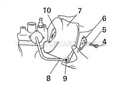 2. Remove bolts, washers and plate (4,5,6) slowly pull the vacuum cylinder (7) to seperate the pipe (8) from the grommet (9) Remove the gasket (10)
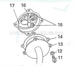
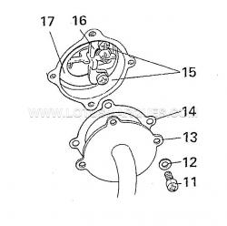 3. Remove set screws, washers, cover and gasket (11, 12, 13, 14) Remove screws (15) lever guide (16) and spring plate (17)
 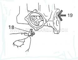 4. To remove (18) 'T' lever valve, push in (19) and lift lever out.
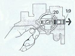 5. Bend 1/8 in (3mm) welding wire and insert into the control piston hole (20) lever the piston until the plug is pushed out (19) lift out piston.
  6. Compress spring (23) and remove the circlip (21) spring seats (22, 24). Remove the seals (25, 26) from the piston(20) and remove seal (27) from the plug (19).
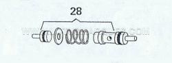 7. If the control piston looks like the diagram above (28) and is in two parts, then this unit if not to old can be serviced by purchasing the following two parts; S7046 and S7011
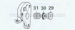
  8. Lift off bush (29) take out the gland seal (30) and shake out the spacer (31).
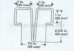 9. Use the rest of the 1/8in welding wire (12in approx) make up a special tool to the dimensions above.
 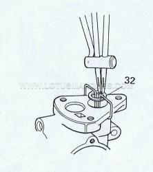 10. Clip the tool under the body flange, with the output piston pushed down the circlip(32) can be removed. A GOOD PAIR OF CIRCLIP PLIERS IS ESSENTIAL. DO NOT SCORE THE BORE OR DROP THE CIRCLIP WHEN REMOVING OR IT COULD RESULT IN BRAKE FAILURE.
 11. Remove the tool to release the spring (33) piston (34) and washer (35).
 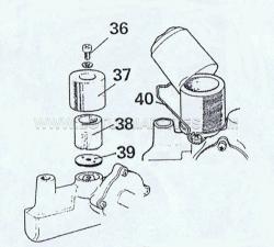 12. Unscrew the set screw (36) and remove the air-filter (38), cover (37) and base washer (39) the early air-filter covers were held on by a circlip.
CLEANING
Cleanliness is now very important, wash your hands and lay out some clean paper to place all the parts on. The new parts in the kit will indicate which old parts are to be discarded.
Clean the remaining old parts with a recognised cleaning fluid or unused brake fluid and let stand to dry.
Look at each part to make sure that it is undamaged and in working order.
Check the piston and bores to make sure there is no sign of corrosion, pitting, scoring or ridges if there is fit a new unit.
RE-ASSEMBLY
 13. Fit new seals to piston (34), lubricate bore and seal with unused fluid and insert the spring (33) into the bore, place the washer onto the piston (35).
  14. Ease the piston and seal into the bore and clip the special tool under the flange. REMEMBER THE CIRCLIP (32) MUST NOT DAMAGE THE BORE SO TAKE EXTRA CARE.
 15. Fit the spacer (31), gland seal (30) and spacer (29) into the bore.
 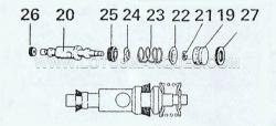 16. Fit new seals (25, 26) to the control piston (20), fit the spring and spring seats, secure with the circlip (21), lubricate the bore and seals with unused fluid.
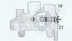 17. Align the control piston hole with that in the valve chest, insert the piston into the bore. Fit the seal (19) onto the plug (27) and push into the bore.
  18. To insert the 'T' lever valve (18) press in the plug (19) so the round end of the lever fits easy in the hole when in the control position.
 19. Fit the spring plate (17), and lever guide (16). Fit screws (15) and position the new gasket (14), and cover (13) over the valve chest and put in the screws (11) and washers (12).
 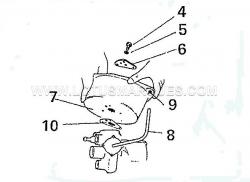 20. Secure unit in bench vice, and position new gasket (10) locate vacuum cylinder (7) on the gasket (10) place the vacuum pipe (8) in the new rubber grommet (9), replace the plate (6) and with the bolts (4) and new copper washers (5) ONLY TIGHTEN THE BOLTS FINGER TIGHT.
 21. With bolts in place but dont tighten them, replace the piston return spring (3) and piston (2) in place, push down through the stroke a few times to line up the bearing bush, try not to move the vacuum cylinder (7) when you remove the piston and spring, tighten the bolts.
 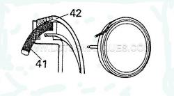 22. Fit the new rubber strip (41) under the leather outer seal with the servo grease.KEEP THE GREASE AWAY FROM HYDRALIC PARTS
 23. Refit the spring (3) and piston (2). Fit a new gasket (43) to cover the plate (44), place the plate on top of the piston, press down and secure with the nuts and bolts. Cover the open ports with tape, if the unit is not being used immediately.
Before dismantling the unit, you will need a 15" length of welding wire and a pair of circlip pliers.
 1. Secure unit in a bench vice, before unscrewing end cover bolts (1) steady end cover (2) against the pressure of the spring (3) before the last bolts are removed.
  2. Remove bolts, washers and plate (4,5,6) slowly pull the vacuum cylinder (7) to seperate the pipe (8) from the grommet (9) Remove the gasket (10)
  3. Remove set screws, washers, cover and gasket (11, 12, 13, 14) Remove screws (15) lever guide (16) and spring plate (17)
  4. To remove (18) 'T' lever valve, push in (19) and lift lever out.
  5. Bend 1/8 in (3mm) welding wire and insert into the control piston hole (20) lever the piston until the plug is pushed out (19) lift out piston.
  6. Compress spring (23) and remove the circlip (21) spring seats (22, 24). Remove the seals (25, 26) from the piston(20) and remove seal (27) from the plug (19).
  7. If the control piston looks like the diagram above (28) and is in two parts, then this unit if not to old can be serviced by purchasing the following two parts; S7046 and S7011
  8. Lift off bush (29) take out the gland seal (30) and shake out the spacer (31).
 9. Use the rest of the 1/8in welding wire (12in approx) make up a special tool to the dimensions above.
 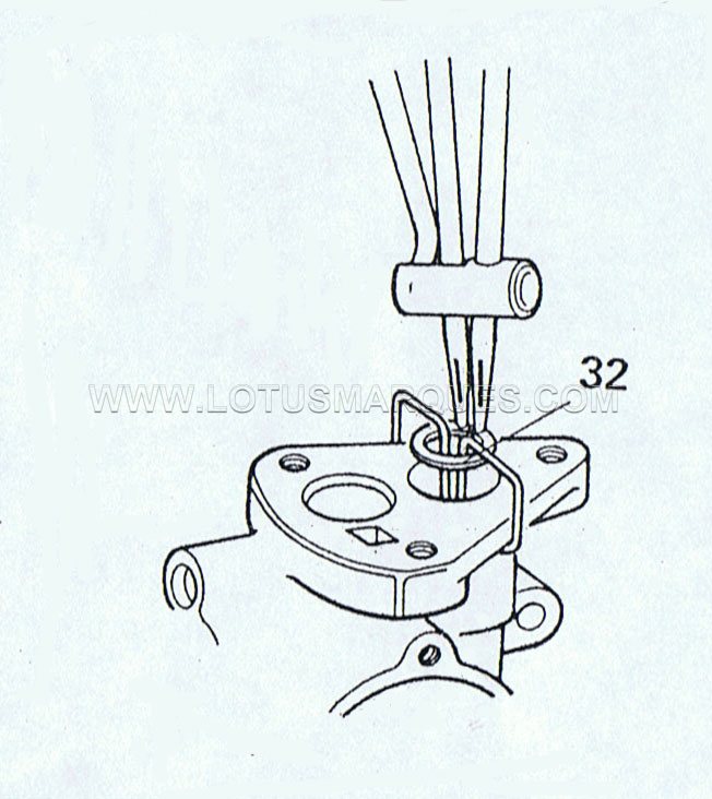 10. Clip the tool under the body flange, with the output piston pushed down the circlip(32) can be removed. A GOOD PAIR OF CIRCLIP PLIERS IS ESSENTIAL. DO NOT SCORE THE BORE OR DROP THE CIRCLIP WHEN REMOVING OR IT COULD RESULT IN BRAKE FAILURE.
 11. Remove the tool to release the spring (33) piston (34) and washer (35).
 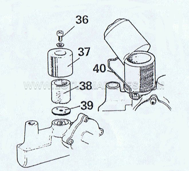 12. Unscrew the set screw (36) and remove the air-filter (38), cover (37) and base washer (39) the early air-filter covers were held on by a circlip.
CLEANING
Cleanliness is now very important, wash your hands and lay out some clean paper to place all the parts on. The new parts in the kit will indicate which old parts are to be discarded.
Clean the remaining old parts with a recognised cleaning fluid or unused brake fluid and let stand to dry.
Look at each part to make sure that it is undamaged and in working order.
Check the piston and bores to make sure there is no sign of corrosion, pitting, scoring or ridges if there is fit a new unit.
RE-ASSEMBLY
 13. Fit new seals to piston (34), lubricate bore and seal with unused fluid and insert the spring (33) into the bore, place the washer onto the piston (35).
  14. Ease the piston and seal into the bore and clip the special tool under the flange. REMEMBER THE CIRCLIP (32) MUST NOT DAMAGE THE BORE SO TAKE EXTRA CARE.
 15. Fit the spacer (31), gland seal (30) and spacer (29) into the bore.
  16. Fit new seals (25, 26) to the control piston (20), fit the spring and spring seats, secure with the circlip (21), lubricate the bore and seals with unused fluid.
 17. Align the control piston hole with that in the valve chest, insert the piston into the bore. Fit the seal (19) onto the plug (27) and push into the bore.
  18. To insert the 'T' lever valve (18) press in the plug (19) so the round end of the lever fits easy in the hole when in the control position.
 19. Fit the spring plate (17), and lever guide (16). Fit screws (15) and position the new gasket (14), and cover (13) over the valve chest and put in the screws (11) and washers (12).
  20. Secure unit in bench vice, and position new gasket (10) locate vacuum cylinder (7) on the gasket (10) place the vacuum pipe (8) in the new rubber grommet (9), replace the plate (6) and with the bolts (4) and new copper washers (5) ONLY TIGHTEN THE BOLTS FINGER TIGHT.
 21. With bolts in place but dont tighten them, replace the piston return spring (3) and piston (2) in place, push down through the stroke a few times to line up the bearing bush, try not to move the vacuum cylinder (7) when you remove the piston and spring, tighten the bolts.
  22. Fit the new rubber strip (41) under the leather outer seal with the servo grease.KEEP THE GREASE AWAY FROM HYDRALIC PARTS
 23. Refit the spring (3) and piston (2). Fit a new gasket (43) to cover the plate (44), place the plate on top of the piston, press down and secure with the nuts and bolts. Cover the open ports with tape, if the unit is not being used immediately.

